
Well, I had a couple of displays from ebay, and one day…. I was going to get one out and have a go, so this is it…

Initially I used an ESP32 devkit, just to run some demos from the excellent library by Bodmer. It was fast and straightforward to use. Seems to run happily at a SPI frequency of 40Mhz. Pushing it to 80Mhz appears to be screen dependent (different displays on the same baseboard). Mostly it works but occasional glitches with text.
So, all good so far. Next step was to figure out what to put on a baseboard. The answer is of course, far too much.
I ended up with:
- ESP32-WROVER, difficult to say no to the extra ram for the price
- MCP23017. Basically, an extra 16-bits of I/O
- 2 x RS485 (TI SN65HV fault protected series)
- 1 x RS232 (MAX3222)
- DS3231 high accuracy RTC, 8-pin version with battery backup
- ADS1115 module
- FM25L16 ferroelectric RAM.
- Rotary encoder (with button) connector for menu navigation/function selection
The FE-ram is for config-stuff and being able to dump data FAST. No programming delay like EEPROM, just flat-out writes at up to 20Mhz and fully non-volatile. The chip cost is higher than conventional flash and goes up steeply on the larger capacity chips. 4M-bit is available but wow, you pay a lot for it. I can do with a basic 2Kx8.
The RS485 uses a fairly standard pinout (75176 style). I opted for the TI versions for the fault protected bus. I need this as it will get used in an environment where people do bad things to the data lines (accidentally of course). All the serial chips are socketed PDIP so easy to change. I did look at full isolation for the serials but at this point its not realistic for me. A sub-board is a possibility later.
Since I wasn’t sure about my power-source, There are two regulator footprint options. It can take either a Holtec HT7833 or an AMS1117-3.3V. I’m currently using the HT7833.
The screen backlight uses a PWM channel and can be fed from the system 3.3V or the pre-regulator voltage. At 5V and full-on, that’s a whopping 200mA. At 3.3V this drops to 50mA and is still perfectly usable. For my 1st application (LiPo driven) I’ll be sticking to the 3.3V useage.
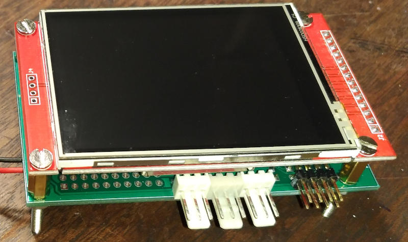
The display and the baseboard are the same size. The display just plugs in and the display mounting holes are matched on the baseboard so a simple spacer between the two and a compact stack is produced.
Above: The connector on the right is the hardware programming header. I didn’t want to fit a serial<->USB on the PCB so its essentially the pins on an ESP-01 that are required for programming. I have a bunch of USB programming boards for ESP-01’s and they work great for this. OTA is also available if the running software supports it. The white connectors are the serial-ports. To the left of them is the breakout for the MCP23017 so 16 bits of I/O and two lots of power/gnd (one each per byte).

Power on the right and the strip of 8 screw-terminals is the 4 ADC inputs plus two lots of power/gnd. The empty 10-way SIL is for the ADS1115 module (waiting…) and to the left of that, a breakout connector for off-board I2C. White connector on the far-side is for the rotary encoder which uses the ESP32 hardware pulse counters. Library here
The pins of the ESP module are all committed (hence the extra I/O). The RTC/ADC/I/O interface IC’s all have interrupt lines connected . If I re-do the PCB, I will wire the INTs to the MCP23017 and use it to let me know something is happening. A bit more latency but two ESP lines freed-up.
One channel of the ADC has some resistor pads on the PCB. If using a battery then incoming voltage (pre regulator) can be monitored.
I do not use the SD-card socket on the rear of the display module. It could perhaps be used by sacrificing the touch-controller chip-select line and wiring it to the SD card select. Also extending the SPI bus to the card socket on the rear of the display module. maybe… maybe not. I have not tried.