
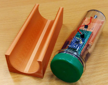
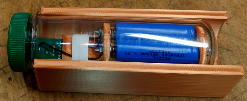
What you should have is a plastic tube with some electronics inside (item on the right of the picture) and a stand for it (on the left of the picture).
To use it as part of your brewing process, it needs to be:
1: Configured for your local WiFi
2: Have its operational parameters set-up.
First thing is to connect it to your WiFi
Unscrew the cap (this one is green) and gently slide out the carrier. It should be free to move inside the tube and come out easily.
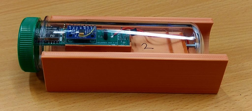
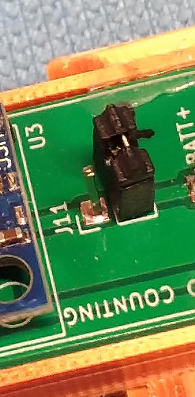
A close-up view of the carrier is as below…
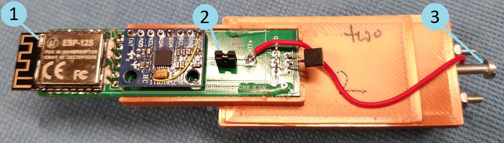
Some items to note are:
1: Small LED (lights blue)
2: This is the power jumper, a pluggable link that connects the battery-power to the electronics. This should be unplugged when the floater is not being used.
3: Balance adjustment screw. When the floater is deployed, this end of the floater is lowest in the liquid. The adjustment screw can be lengthened and shortened to set the correct reference-angle in water (more on this later).
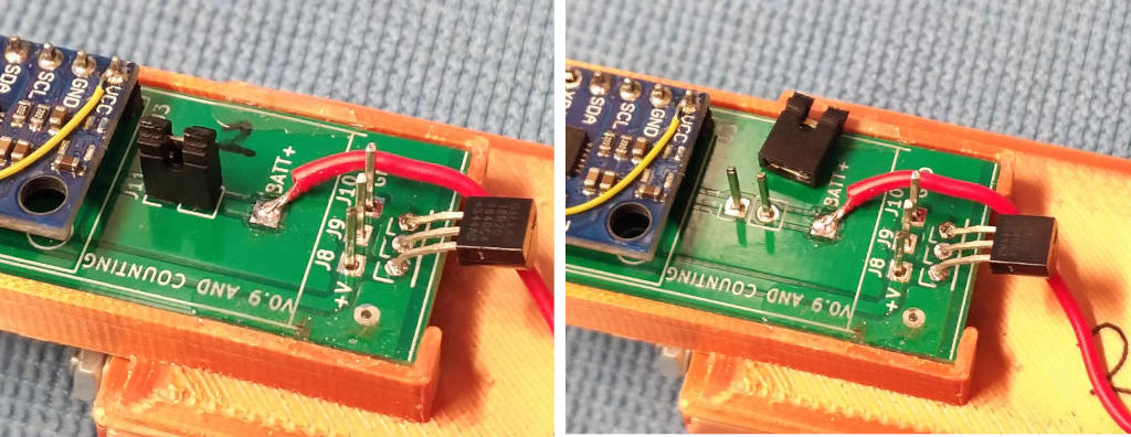
A closer view of the power-link shown below.
Left-pic. System is ON
Right-pic. System os OFF. Slide the link onto ONE pin for storage
Connecting to local WiFi:
You need to have the local WiFi password handy and a phone/computer/laptop with WiFi.
Accessing configuration modes is by a timed sequence from power-on. The orientation of the floater 10-seconds after the power-link is connected determines the configuration mode.
Plug on the power-link to start up the electronics. The blue LED will briefly light as the power is turned on.
Slide it back in the tube (adjustment screw towards the curved end) and stand it up on the green cap. 10-sec from power-up, a continuously blinking blue LED should be happening (near the green cap-end).
Use your phone/computer/laptop to look at the local WiFi networks in the area.
Each floater has an ID-number. In the pictures above it is 2. If the LED is blinking on/off, you should be able to see a new WiFi network called floater-2 where the number is the same as on the floater body.
Join the network (no password required).
Depending on your system, it may automatically launch a web browser and show you the WiFi setup page. If not, open a browser window and type in the address bar http://192.168.4.1
This will load the WiFi setup page. When setting up floater-3, it looked like this…
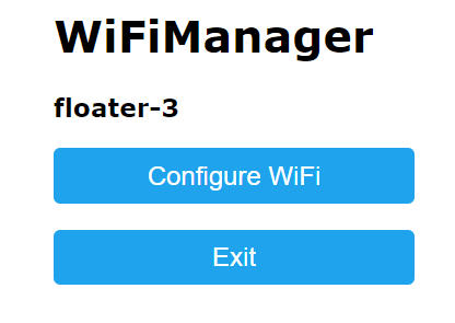
Select configure WiFi then after 3~4 seconds a new page will load with the local detected WiFi networks shown. Click on the network you want the floater to join, enter the password and save it.
Observe the blinking LED. It will continue blinking for several more seconds and if the floater connects OK to the requested WiFi, the flashing will stop after 3-rapid blinks.
If instead you get a long (3-seconds) solid ON of the LED, the connection has failed and you need to try again. You have to remove the power link wait for 5-sec then start again as above.
Once the WiFi connection is successful (three rapid blinks), remove the power link. The WiFi setup will be remembered every time the floater is powered-on.
The next step is to configure the floater’s operational parameters. This is done by another timed sequence, similar to entering WiFi config mode.
This time, when you plug-on the battery link, by the time 10-sec has elapsed the floater must be horizontal and upside-down. It can be in the holder or just in your hand but hold it as horizontal as possible and stationary.
After 10-seconds the blue LED should begin flashing again. If your holding it, its OK to move it now so put it in the tube as shown in the picture.
Look at the local WiFi networks again and a new one called floater2_cfg should appear.
Join this network (no password required).
Open a web browser and in the address bar, go to http://192.168.4.1
This should open a web page to allow the operational setup of the floater.
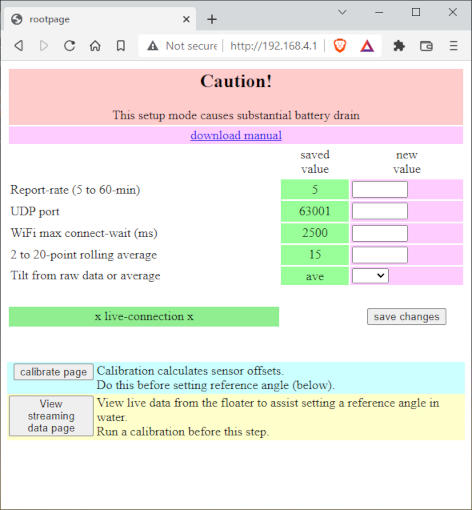
Report-rate: is how often the floater sends data. This is now adjustable from 1 to 60-min.
5 is a reasonable minimum, or longer if you want. Lower than 5-min is not recommended because of the battery drain.
UDP port: This is for the WiFi network transactions. Don’t change this unless you have a very good reason (default 63001).
WiFi max wait: 3000 is a good starting point. It depends on your WiFi network so its a try-it-and-see. 1000 is probably too low, 10000 too high
Rolling average: If you are going to use this, how many samples (2 to 20) are used to create the average.
Tilt from raw data or average: When the tilt-angle is calculated it can be from the averaged values, or from the raw-data.
If you change any of the items above, click the save changes button. The values in the green column will update to show the newly saved values.
Before using the floater, a calibration is required so to do this, make sure the carrier is in the tube, in its stand and batteries facing DOWN.
When the positioning is good, click on the calibrate page button.
This shows you how to position the floater and at the bottom of the calibrate page, click on the start calibration button.
A text-box will open and tell you whats happening, it only takes 2~3 seconds to calculate the required data. When complete another web-page auto-loads like…
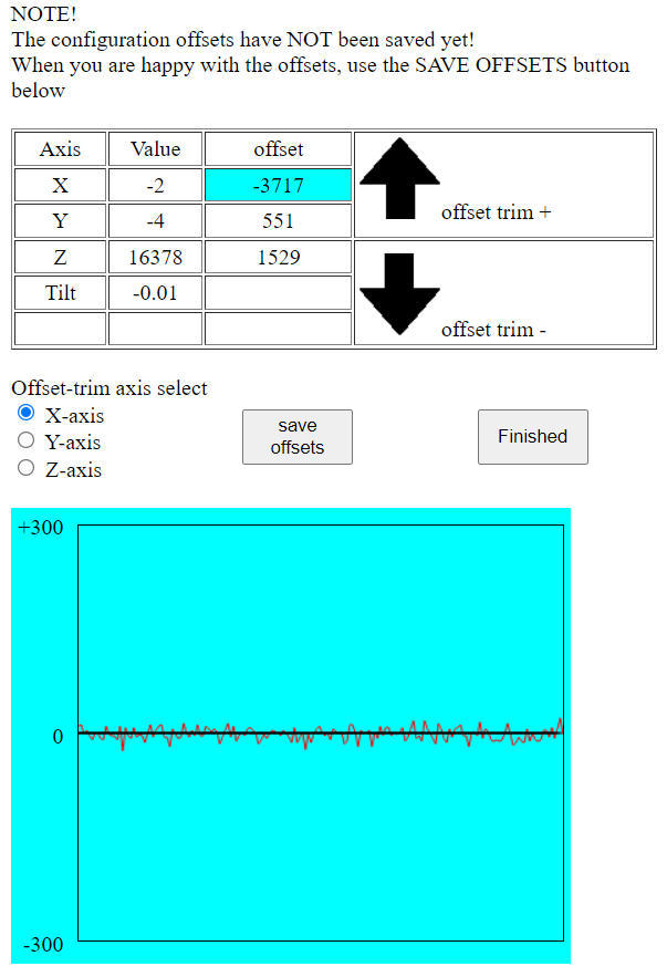
The page opens with the X-axis selected and a jiggly line start to march across the screen from right to left. This is the raw-data from the respective sensors (x/y/z).
In an ideal-world, the line would be flat. However the sensors produce a degree of signal noise which is the non-flat jiggles.
select the X,Y,Z axis in turn and use the offset-trim button to (as much as possible) move the marching line (as it comes in from the right) up or down so it ends up being as symmetrical as possible around the zero line.
The one in the picture is good. Sometimes the line ends up more above or below but just get it as good as possible.
After all three axis have been optimised click on the save offsets button.
The sensor offset values are now stored so each time the floater is powered-on, these are recalled for use.
This sets the reference horizontal plane and its used as 0-deg of roll and tilt.
The tilt angle is calculated from the x/y/z values and this is also displayed on the web page table (in the picture).
The final step is to set the reference angle in plain water.
As well as the live x/y/z data being shown, tilt angle is also displayed. It wont be static but if you did a good job with the offset-trims above, it might be jumping about by +-0.05-deg. Keep it below +-0.1-deg if possible.
The target angle is -65 degrees in plain water (which is at 20 Deg C, +-0.2 Deg C).
With the floater sealed-up ready to deploy (cap on, snug but not over-tight), gently place it it the water (so it settles quickly) and look at the tilt angle on the live web-page.
If the angle is greater than -65, ie -70, this is too steep, too close to vertical.
This means the adjustment screw (shown earlier) needs to be longer to move the weight away from the curved end of the clear tube.
Take the floater out of the water, dry it then carefully remove the cap. Hold the tube horizontal, cap slightly down so that any water in the threads does not fall into the tube or get onto the carrier.
Slide out the carrier and adjust the screw by a max of two-turns anti-clockwise (to make the projecting part longer), then reassemble and check again. Keep doing this till the tilt-angle is displayed as -65 degrees (+- 1).
When completed, click on the Finished button (beside the save offsets button).
At this point, remove the power-link to power down the floater at least once before it is deployed.
The floater is now ready to deploy (when powered on again). If not being used till later, park the power-jumper on just one of the pins.
The WiFi and calibration data will be recalled and applied when next powered-on.
When powered ON next time, keep it horizontal, batteries DOWN to stop it entering one of the configuration modes. After 10-sec, the blue LED should show 3 rapid blinks to indicate the WiFi connection is successful.
If the calibration process took a long time, it may be worth recharging the batteries before use. The setup and calibration are high power-drain operations.